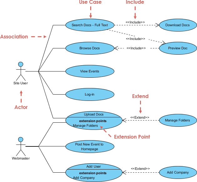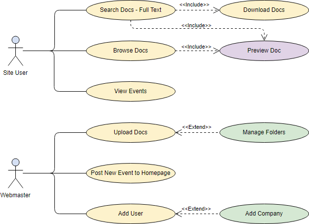


Business use cases represent the processes that a business performs, and business actors represent roles with which the business interacts, such as customers or vendors. (Use Case diagrams, which will be discussed next, focus on the automated processes.) Business Use Case diagrams show the interactions between business use cases and business actors.
#Use case diagram visual paradigm manual
They do not differentiate between manual and automated processes. They answer the questions " What does the business do?" and " Why are we building the system?" They are used extensively during business modeling activities to set the context for the system and to form a foundation for creating the use cases.īusiness Use Case diagrams are drawn from the organizational perspective. Business Use Case diagrams are used to represent the functionality provided by an organization as a whole. The following resources may help you to learn more about the topic discussed in this page.This is a business use case diagram example.

The source shape and the newly created use case are connected.Select Association -> Use Case from Resource Catalog.Release the mouse button until it reaches your preferred place.Press on the Resource Catalog button and drag it out.Move the mouse over a source shape (e.g.Finally, name the newly created actor when it is created.īesides creating a use case through diagram toolbar, you can also create it through Resource Catalog: To draw an actor in use case diagram, select Actor on the diagram toolbar and then click it on the diagram pane. Finally, name the newly created system when it is created. To create a system in use case diagram, select System on the diagram toolbar and then click it on the diagram pane. The Location field enables you to select a model to store the diagram. Enter the diagram name and description.In the New Diagram window, select Use Case Diagram.Select Diagram > New from the application toolbar.Perform the steps below to create a UML use case diagram in Visual Paradigm.
#Use case diagram visual paradigm how to
In this page, you will see how to draw use case diagram with the UML tool. You can draw use case diagrams in Visual Paradigm as well as to document the use case scenario of use cases using the flow-of-events editor. goals) as well as the actors that interact with those functions. Use case diagram is a kind of UML diagram that enables you to model system functions (i.e.


 0 kommentar(er)
